Guides / Process
Trim and Form Tooling for OSAT Lines: Parts, Steels and Sharpening
October 26, 2026
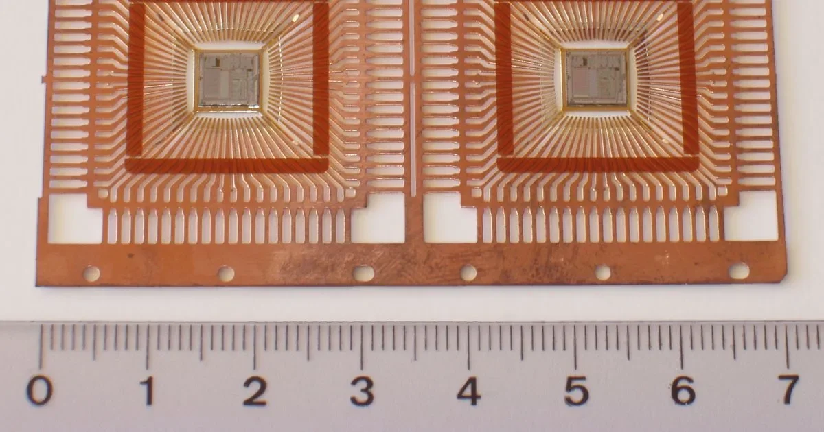
After a package is molded, it is still part of a strip. Leads are tied together by a thin web of metal called a dambar. Excess molding compound surrounds the body and the leads stick out straight. A trim and form tool does the last mechanical work: it cuts the dambar and the surplus, separates the unit from the strip and bends the leads into the shape the customer’s board needs.
The tool is a precision piece of work. Its parts cut metal a fraction of a millimetre thick, within micrometers of the clearance that gives a clean edge, thousands of times an hour. It is also a wear item, and the parts of it that wear are made by machine shops. This guide covers the parts, the materials and the questions to ask.
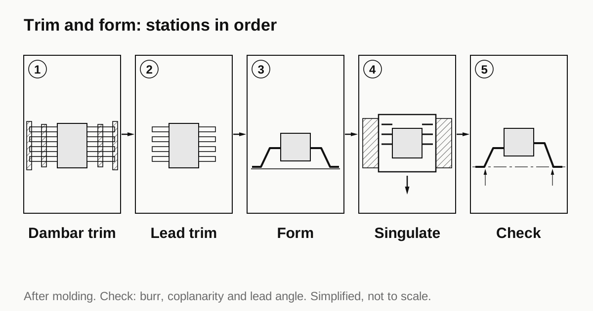
What the tool does, station by station
A trim and form tool is often progressive: the strip advances one pitch at a time through a series of stations in a single press stroke.
- Dambar trim. Punches cut the web between the leads.
- Lead trim. The leads are cut to length, and the tie bars that held the frame are removed.
- Form. Punches and dies bend the leads to gull wing, J lead or another shape.
- Singulate. The finished unit is cut free and drops out.
Some processes combine these or add a step for lead tip finishing or coining. The details depend on the package type: QFP, SOIC, TSOP, SOT and others each have their own geometry.
Parts of the tool and what they do
| Part | Function | Typical material | Critical feature |
|---|---|---|---|
| Punch | Cuts or forms the lead | Tool steel, carbide | Cutting edge, length, clearance |
| Die | Mates with the punch | Tool steel, carbide inserts | Opening size, edge, flatness |
| Stripper plate | Holds the strip flat and pushes it off the punch | Hardened steel | Hole position, flatness |
| Guide plate | Aligns punches to dies | Hardened steel | Bore position, finish |
| Pilot | Locates the strip by its holes | Hardened steel | Diameter, concentricity |
| Spring plate and backing plate | Carry loads | Alloy steel | Flatness, parallelism |
| Form blocks | Shape the leads | Tool steel, coated | Contour accuracy, finish |
Each is a small part with a few critical features. Machine shops usually make them from the tool designer’s drawing.
Steels and carbide
Cutting thin copper alloy or Alloy 42 lead frame wears the edge, and the choice of steel sets how often the tool needs sharpening.
SKD11 or D2 type steel. The common choice for punches and dies, hardened to 58 to 62 HRC. Good wear resistance and affordable. See SKD11, SKD61 and S50C for jigs and tooling.
Powder metallurgy tool steels. Finer carbides, better wear life and toughness for the same hardness. Used where regrinds must be less frequent.
Tungsten carbide. Very hard, long wearing, brittle. Used for inserts at the cutting edge on high volume tools. Cutting carbide takes wire EDM and diamond grinding, and a shop that cannot do both cannot make the part.
Coatings. Titanium nitride and similar coatings extend the life on form blocks and punches. A coating shop adds time and risk, and it changes the surface and the size by a few micrometers.
For the hardening step see heat treating tool steel fixtures.
Clearance and edge quality
A punch cuts by shearing metal against the die edge. The gap between them, the clearance, controls the cut. Too tight and the edges wear fast and tools gall. Too loose and the cut edge has a large burr and a rolled shoulder. For a thin lead frame, the clearance is a few micrometers to about ten micrometers per side, set by the tool designer for the material and thickness.
That tiny clearance puts demands on the machining: punch and die openings are made by wire EDM, often with several skim passes, and finished by jig grinding or lapping. The shop’s job is to hit the stated size and shape and to keep the pair concentric. See wire EDM for precision jig plates and jig grinding locating pin and dowel holes.
A burr on a trimmed lead is a defect, since a lead that is burred can short to a neighbour or fail a coplanarity check. Burr height is measured under a microscope, and customers set the limit in micrometers.
Accuracy and alignment
Position matters across the whole tool. Guide bushings and posts locate the upper and lower halves. Punches must hit the die openings within the clearance, and the strip must be placed in each station within the same budget. A position error of a few micrometers on a punch can mean a one sided cut, fast wear on that side and a bad lead.
Specify the position of cutting features to the same datum, usually a locating bore, and give the tolerance in a feature control frame. Accumulated tolerance across several plates deserves a check. See tolerance stack-up for fixtures.
Need a quote for this part? Get a quote
Sharpening and spare parts
Cutting edges wear and must be reground. Each regrind removes a small amount of the punch length, so the tool is designed with stock for a number of regrinds, and shims or adjustment compensate for the lost height. After the final regrind, the punch is replaced.
This turns punches and dies into scheduled spares. A plant that runs a tool continuously should hold spare punches and dies for each regrind cycle, and a spare set for each critical station. The reorder rule is to place an order when the last spare goes into the tool, not when it fails. Spares and consumable planning covers how to calculate the quantity.
Ask the tool designer, or the plant that owns the tool, for three numbers: the stock allowed for regrind, the maximum number of regrinds and the usual shots between regrinds. A shop that makes a replacement punch needs the first two to put the right length on the part.
What the lead frame does to the tool
The metal being cut sets the wear. Lead frames are stamped or etched from copper alloys or from iron nickel Alloy 42, in thicknesses typically from about 0.1 to 0.25 mm. Copper alloys are soft and tend to leave burrs and smear on the punch. Alloy 42 is harder and stiffer, wears edges faster and springs back more after bending, so the form station is shaped to overbend by a small angle. Plating on the leads, tin or a nickel palladium finish, adds a thin layer that can flake and collect on the punch. A tool that works on one frame material can need new clearances, new coatings or a different steel on another, which is why a replacement part needs the frame material on the drawing.
Monitoring wear in the plant
Plants watch the tool through the product. Burr height, lead length, coplanarity and lead angle are measured at intervals, and a drift in any of them signals wear before a defect ships. Counting shots per tool and recording them against measured quality gives the regrind interval for that frame and package, which is far more useful than a number from a data sheet. A shop that makes the parts benefits from the same data: if a punch set lasts a hundred thousand shots on one frame and fifty thousand on another, the next order can specify a steel or coating to match. Share the numbers in the RFQ when they exist.
Making replacement parts
Most orders for trim and form parts are replacements: a punch that has worn out, a die with a chipped edge. The drawing may exist or may not. The risks are the same as for any replacement part. Material and hardness must match, the clearance must match and the length must match. A punch made from a different steel at a different hardness cuts at the same size and wears at a different rate. Changing the material without a trial is a risk to the production line.
First article inspection matters here. Run the first punch in a trial before ordering a batch. See first article inspection.
What to ask a shop
- Have you made punches and dies with sub 0.01 mm clearance, and can you show the measurements?
- Which wire EDM and which grinder will cut and finish the openings?
- Can you machine and grind tungsten carbide, or do you use a partner?
- Who heat treats the steel, and how do you control distortion on thin plates?
- How do you check burr height and edge condition?
- Can you hold a record of each tool part by serial number?
Trim and form tooling is one of the part families in our guide to semiconductor jigs and fixtures.
Checklist before you send the RFQ
- Tool drawing or part drawing with the package type
- Material and hardness, or carbide grade
- Punch and die clearance and the opening tolerance
- Critical positions and the datum scheme
- Surface finish and edge condition
- Coating, if any
- Regrind stock and the number of spares needed
- First piece trial and who runs it
Send them with the drawings through the RFQ form. We place it with a partner shop and send one itemised quote within 24 business hours.
Frequently asked questions
What does a trim and form tool do?
After a package is molded on a lead frame, the tool cuts away the excess molding material and metal that holds the leads together, which is the trim, then bends the leads into their final shape, such as gull wing or J lead, which is the form. It is a progressive or multi station tool that runs in a press at high speed.
Can an outside shop make the whole tool?
Some tool makers build complete tools to a package drawing. Most machine shops make the detail parts of a tool: punches, dies, strippers, guide plates and pilots, to a drawing from the tool designer or the owner. The two tasks need different skills, and the quote should say which is being bought.
How long does a punch last between sharpenings?
It depends on the lead frame material, the thickness, the clearance and the press speed, so there is no fixed number. Plants track shots between regrinds and record them. The tool design should allow a set number of regrinds and give the amount that can be removed each time.
Need a quote for this part?
Send the drawing. We quote the finished parts, place the work with a partner shop in Vietnam and reply within 24 business hours.
Get a quoteMore on process
- JEDEC Matrix Trays and Custom Carrier Trays: When Machined Replaces Molded
- Designing a Package Nest: Pocket Size, Clearance, Lead-In and Datum
- Planning Production When Urgent Spares and New Jigs Share the Machines
- Semiconductor Jigs and Fixtures: Which Part Family, What to Specify, What Fails and Who Makes It
All guides and the sourcing glossary.