Guides / Process
Designing a Package Nest: Pocket Size, Clearance, Lead-In and Datum
November 21, 2026
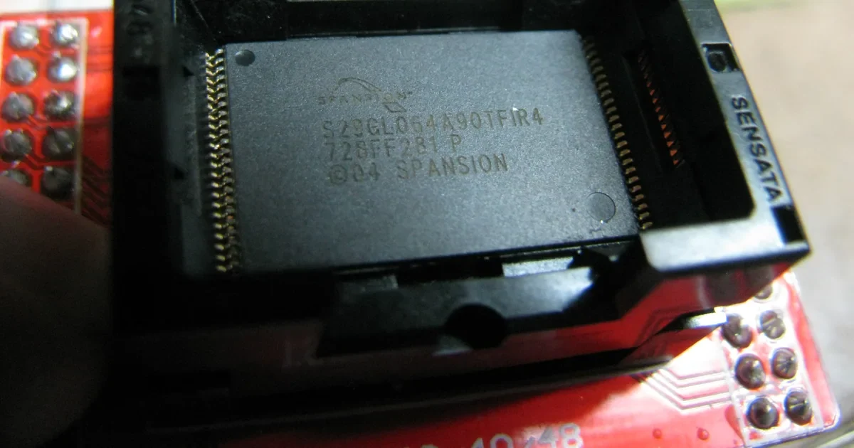
A package nest is a pocket that holds a device in a known place for the next step. Size the pocket from three numbers: the largest package the supplier’s drawing allows, a clearance so that package never jams and the wear you accept before the pocket is replaced. Then check that the smallest package, sitting hard against one wall, still lands inside what the next stage can capture. This post is part of our guide to semiconductor jigs and fixtures and works through that method with one example.
The example numbers are assumed for illustration. They are not a standard and not a recommendation for any package.
What you need before you start
You need four inputs, and a nest drawn without all four is a guess.
- The package outline drawing with its body tolerance, not the nominal size from a data sheet table.
- The capture window of the next stage: the lead-in of the socket, the vacuum tool’s search area or the handler’s pick tolerance. This is the number your nest must not use up.
- The temperature range the nest will see, including any hot or cold test.
- The wear you will accept before the nest is scrapped, and the number of cycles you expect to reach it.
The first two usually come from different companies. The package maker owns the outline, the equipment maker owns the capture window and the plant owns the temperature and cycle count. That split is why a shop cannot size a nest from a part picture alone.
Why package tolerance dominates the design
Leadless packages carry a body tolerance that is large beside their pitch. A 2005 paper at the Burn-in and Test Socket Workshop described a common profile tolerance of ±0.15 mm about the perimeter, against pitches as small as 0.4 mm and moving toward 0.25 mm. A handler patent from Delta Design puts it as handlers having to cope with body tolerances of up to 0.2 mm, and describes the trade-off plainly: a tight opening sticks devices on the high side of the tolerance, and a larger one lets devices move and raises continuity failures.
That trade-off is the whole job. A pocket sized for the largest package lets the smallest one wander, and a pocket sized for the smallest one jams the largest. The width of the wander is the number you design against.
The procedure in six steps
- Fix the package limits. Take the largest and smallest body size in each axis from the outline drawing. Fails when you use the nominal size and the real lot sits at the high limit.
- Choose the clearance. The clearance is the gap between the largest package and the pocket when the pocket is at its smallest. In the 2005 socket example it was 0.010 mm. Choose it from how the package arrives: a part dropped by a plunger needs more than a part placed by a vacuum tool. Fails when the clearance is so small that a slightly bowed package or a particle jams the entry.
- Add the pocket edge tolerance. The largest pocket equals the largest package plus the clearance plus twice the edge tolerance per side, which is the formula the 2005 paper uses. The same paper’s example used 0.025 mm per side and showed a roadmap to 0.013 mm. Fails when the drawing gives a tolerance the shop cannot hold or measure on the pocket.
- Work out the free play. The smallest package can sit against either wall, so its largest offset from center is the pocket size minus the smallest package, divided by two. Fails when you forget that the free play is per side and compare the total with a per side capture window.
- Add wear and temperature. Add the opening growth you accept from wear and the thermal growth of the plate. Fails when the nest is checked only new and at room temperature.
- Compare with the capture window. The remaining margin is the capture window minus the worst offset. If it is thin, tighten the clearance or the edge tolerance or change to a method that corrects the position, such as alignment pins or optical alignment. Fails when nobody has the capture window in writing.
A worked example with assumed numbers
The package is 7.00 mm square with a body tolerance of ±0.15 mm, so it measures 6.85 to 7.15 mm in each axis. The clearance is 0.05 mm and the pocket edge tolerance is 0.01 mm per side. All of these are assumed.
| Quantity | Calculation | Result |
|---|---|---|
| Smallest pocket | 7.15 + 0.05 | 7.20 mm |
| Largest pocket | 7.15 + 0.05 + 2 x 0.01 | 7.22 mm |
| Free play, new | 7.22 - 6.85 | 0.37 mm in total |
| Largest offset from center, new | 0.37 / 2 | 0.185 mm per side |
| After 0.03 mm of opening wear | (7.22 + 0.03 - 6.85) / 2 | 0.200 mm per side |
| Hot, 100 K above room, aluminum plate | pocket 7.22 grows 7.22 x 23e-6 x 100 | +0.017 mm, offset 0.193 mm per side |
| Hot and worn | (7.22 + 0.017 + 0.03 - 6.85) / 2 | about 0.208 mm per side |
| Cold, 65 K below room, aluminum plate | smallest pocket 7.20 shrinks 0.011 mm | clearance to the largest package 0.039 mm |
Calculated from the assumed inputs above. Thermal growth uses 23 micrometers per meter per kelvin for aluminum at 25 °C (Engineering ToolBox); package expansion is ignored here and must come from the package maker.
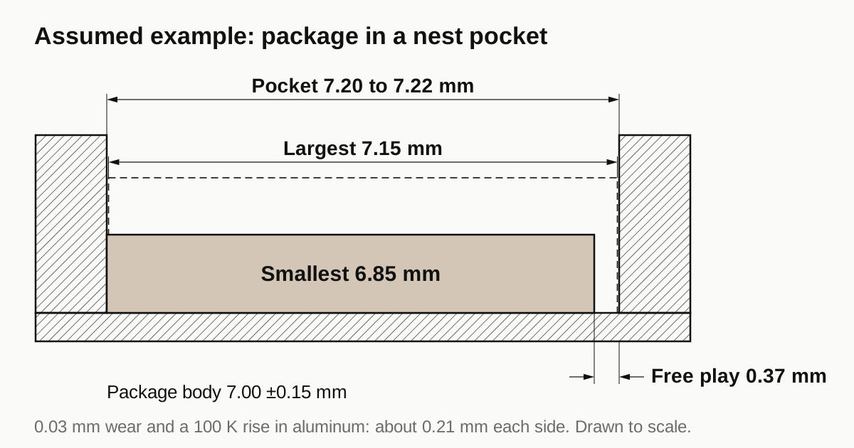
If the next stage can capture 0.25 mm per side, which is also assumed, the worst case leaves about 0.04 mm of margin. That is thin enough to justify a tighter edge tolerance or a replacement limit at 0.03 mm of wear. If the capture window were 0.15 mm, this nest would fail on day one and the answer would be pins or optical alignment, not a better pocket.
Need a quote for this part? Get a quote
Temperature, material and wear
Material changes the numbers. Engineering ToolBox lists aluminum at about 23 micrometers per meter per kelvin, acetal (POM) at 85 to 110 and glass-reinforced epoxy at 36, at 25 °C. A POM nest of the same size would grow about four times as much as the aluminum one over the same rise. For hot or cold test, check the clearance at both ends of the range, not only at room temperature.
Wear depends on where the package touches. A 2004 socket workshop paper explains that when the package is pressed against the socket floor as a hard stop, mold compound particles, laser mark dust and tin transfer onto the floor over thousands of insertions, and the floor must withstand the shock of the plunger. The pocket walls see the same debris. Treat the wall as a wear part: set a replacement size on the drawing, and see why jigs and fixtures fail on the line for the failure side.
For static, remember that a plastic nest holds charge and attracts particles. A semiconductor industry article notes that insulating plastics hold charge for long periods and that grounding cannot remove charge from an insulator. State the surface resistance range you need, as covered in ESD materials and coatings.
Lead-in, datum and holding method
Lead-in. A chamfer or radius at the pocket mouth catches a package that arrives off center. We found no public standard that gives a lead-in angle or depth, and the right value depends on how the package arrives. Take it from the equipment maker’s drawing or a sample nest, and trial it on the machine.
Datum. Put the pocket position on the same datum as the locating pins or bore that mounts the nest, not on the plate outline. The position of the pocket to that datum adds to the free play. For how stacked tolerances combine, see tolerance stack-up on assembled jigs and fixtures.
Holding method. A pocket that only locates needs a way to keep the package down: gravity, a vacuum port, a spring clamp or a lid. Each changes the pocket depth and the contact faces, so decide it before the pocket depth.
What good output looks like
A good nest drawing states the package limits it was sized for, the pocket size with its tolerance, the replacement size, the datum, the material with its surface resistance, the temperature range and the capture window it must leave. A good shop answer states what it can measure on the pocket and with which instrument. If the shop cannot measure the pocket to a fifth of its tolerance, the number on the drawing is a hope.
Checklist before you send the RFQ
- Package outline drawing with body limits and the revision used
- Capture window of the next stage, per side, in writing
- Temperature range and number of cycles to replacement
- Pocket size, edge tolerance and the replacement size
- Datum scheme shared with the mounting features
- Lead-in geometry from the maker’s drawing or a sample nest
- Material, finish and surface resistance range
- A trial lot on the real machine before the batch
Send it with the drawing through the RFQ form. We reply within 24 business hours with a quote or a plain no, and the guide to semiconductor jigs and fixtures shows where the nest sits among the other part families.
Sources
- BiTS Workshop 2005, session 8: contactor alignment worked example (pocket formula, ±0.15 mm profile tolerance, roadmap values)
- US 10,852,321 B2, Test handler head having reverse funnel design, Delta Design (body tolerance up to 0.2 mm, opening trade-off)
- BiTS Workshop 2004, session 6: alignment of leadless packages, hard stop wear and debris
- Engineering ToolBox, linear expansion coefficients (aluminum, POM, glass epoxy)
- Semiconductor Digest, controlling electrostatic contamination in cleanroom manufacturing (insulators hold charge, grounding limits)
Frequently asked questions
How much clearance should a package nest pocket have?
There is no single figure. The pocket must pass the largest package that the supplier's drawing allows and still hold the smallest one inside the accuracy the next stage can capture. A published socket example used 0.010 mm between the largest device and the pocket. Start from your package drawing and the capture window of the contactor or nozzle, then add the wear you will accept.
What is the usual tolerance on a package body?
A 2005 socket workshop paper called a profile tolerance of ±0.15 mm about the perimeter common for leadless packages. A handler patent from Delta Design says handlers must cope with body tolerances of up to 0.2 mm. Read the outline drawing of your own package, because both figures are examples and not limits for every package.
Does thermal expansion matter for a nest?
Yes, on hot or cold test. Aluminum expands about 23 micrometers per meter per kelvin, and plastics such as POM expand roughly four times as much. A 7.2 mm pocket in aluminum grows about 0.017 mm over a 100 K rise, which is small beside the package tolerance but large beside a tight clearance.
Who sets the lead-in angle of a nest?
The handler or equipment maker usually does, because the angle depends on how the package arrives and on the capture window of the next stage. We found no public standard that gives an angle. Ask for the maker's drawing or a sample nest and copy the geometry, then confirm it with a trial on the real machine.
Need a quote for this part?
Send the drawing. We quote the finished parts, place the work with a partner shop in Vietnam and reply within 24 business hours.
Get a quoteMore on process
- JEDEC Matrix Trays and Custom Carrier Trays: When Machined Replaces Molded
- Planning Production When Urgent Spares and New Jigs Share the Machines
- Semiconductor Jigs and Fixtures: Which Part Family, What to Specify, What Fails and Who Makes It
- Lead Frames Explained: The Metal Skeleton Inside the Package
All guides and the sourcing glossary.