Guides / Quality
Building a Measurement Room That Passes a Semi Audit
November 15, 2026
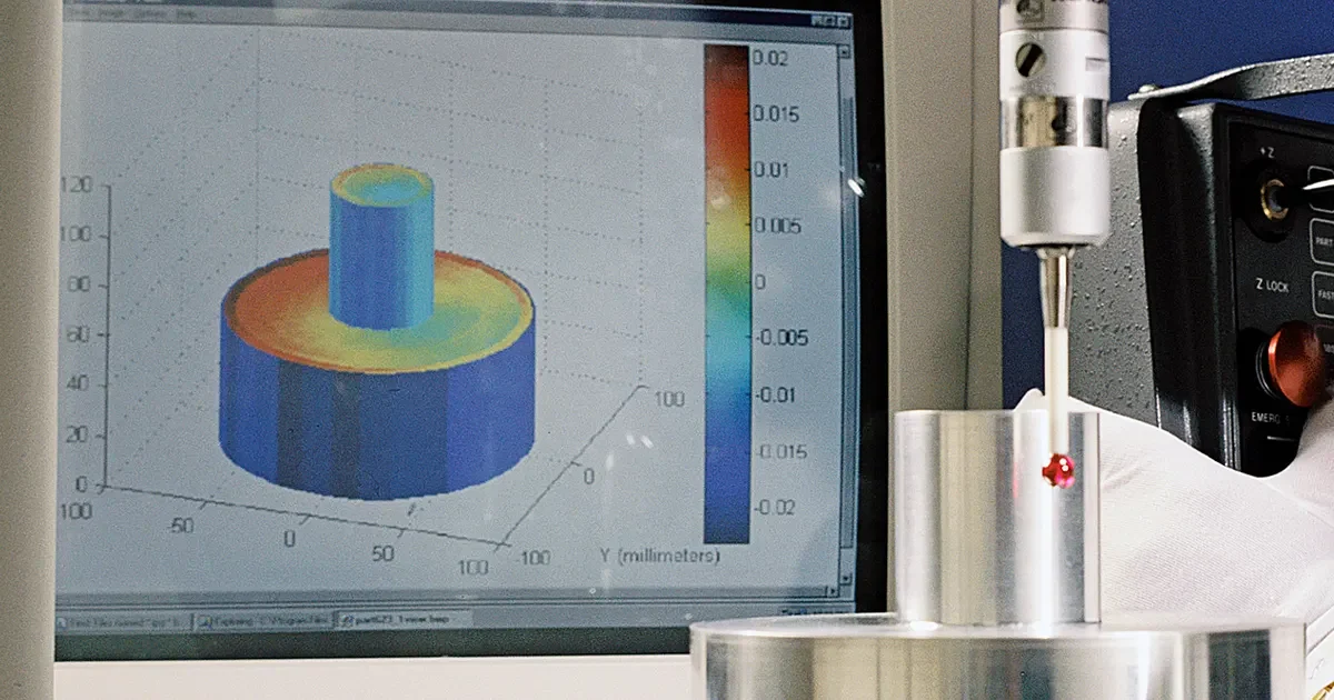
A measurement room passes an audit when four things can be shown on paper: the temperature and humidity stay inside the CMM maker’s limits, the floor is quiet enough for that machine, the machine’s own accuracy test is current, and the shop knows how to use temperature compensation on the parts it measures. The room is the cheapest of these to get wrong and the most expensive to explain afterwards. No OSAT or tool maker we found publishes a measurement room specification for its suppliers, so this guide is built from CMM maker installation sheets and metrology sources, and each buyer’s supplier quality engineer has the last word.
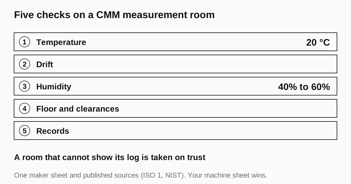
Start from the maker’s installation sheet
Every CMM maker publishes the conditions under which its accuracy figure holds. One example is the Zeiss CONTURA G2 installation instruction, a bridge machine for the shop and quality room. It is one model from one maker, so treat the numbers as an illustration of what such a sheet contains, not as a standard.
| Item | Zeiss CONTURA G2 installation sheet |
|---|---|
| Ambient range for operational readiness | +17 °C to +35 °C, 40% to 60% humidity without condensation |
| Temperature range for the stated accuracy | 18 °C to 22 °C |
| Temperature change allowed | 1.0 K per hour, 1.5 K per day, 1.0 K per meter |
| Software condition | Workpiece and CMM temperatures and the expansion coefficient of the workpiece are entered into a correction program |
| Room height | Machine height plus at least 200 mm overhead (3000 mm minimum for this model) |
| Wall distance | At least 800 mm between machine and wall |
| Floor vibration | Permissible curves are in the sheet. Measure the real floor, because heavy machinery, vehicles and stamping or forging machines in adjacent rooms are the usual cause |
Two points follow for a Vietnamese shop. First, the wide operating range and the narrow accuracy range are different promises. A machine can run at 30 °C and still be outside its accuracy specification. Second, the drift limits matter as much as the band. An air conditioner that swings 3 °C over a 20 minute cycle can keep the average at 20 °C and still fail the per-hour limit.
Why 20 °C, and what a degree costs
ISO 1 fixes 20 °C as the standard reference temperature for geometrical specifications and their verification. Drawing tolerances are meant to be true at 20 °C, so a part measured at another temperature has to be corrected or the room has to be at 20 °C.
The size of the error is simple arithmetic. NIST’s thermal expansion paper by Ted Doiron gives the expansion coefficient of a steel gage block as 11.5 × 10⁻⁶ per °C, with a tolerance of ±1 × 10⁻⁶. Our calculation from that figure: a 100 mm steel feature grows about 1.15 µm for each degree above 20 °C. A commonly tabulated linear coefficient for aluminum is 23.1 × 10⁻⁶ per K at 20 °C, so a 100 mm aluminum feature grows about 2.3 µm per degree.
Put that on a real part. A 300 mm aluminum jig plate measured 2 °C above 20 °C reads about 14 µm too long (300 mm × 23.1 × 10⁻⁶ × 2). If the drawing tolerance is ±0.01 mm, the thermal error alone is larger than the tolerance. Mitutoyo’s training material makes the same point with a 20 inch gage block at 21 °C, which grows about 0.0002 inch.
Temperature compensation is not a room substitute
Modern CMMs measure the workpiece temperature and correct for it, and Mitutoyo states that the CMM accuracy relies on its use. Its example CMM is specified across 16 to 26 °C on the condition that compensation is used properly. The same handout warns that misuse can create a false temperature difference and large errors. For a shop this means:
- enter the correct expansion coefficient for the actual material and grade, not a generic “steel” value, since the range for steel is wide;
- keep the part sensor on the part or on nearby fixturing at the same temperature, and not on a warm vice;
- let parts soak after machining before a tight measurement, and measure parts and masters of similar material where you can.
Mitutoyo’s own calibration laboratory is held at 20 ±0.1 °C with 0.03 °C per hour and 0.03 °C per meter, and the NIST reference CMM sits in a room at 20 ±0.01 °C. Those are calibration laboratory conditions. A production shop needs the conditions its tolerance and its machine require, no more, and the difference is a cost decision.
Build the room around the heat
An auditor reads a room the way a thermal engineer would. Mitutoyo’s list of ways to fight temperature is a useful design checklist:
- reduce traffic and large doors, so use a lobby or a separate room away from the loading bay;
- reduce heat sources, which means lights, people and equipment. Mitutoyo’s step gauge example keeps the CMM controller in an adjacent room and automates the measurement to remove operator body heat;
- eliminate direct blowing of air on the machine or the part, which is also on Mitutoyo’s list, so check where the supply diffusers point;
- monitor the environment with alarms, and keep the lights on all the time so the room does not cycle;
- match materials between gauge and part, and allow soak time.
Our own advice, not a published requirement: keep the air conditioning running 24 hours a day including holidays. Tet is the obvious example, since a room switched off for a week returns to a different state than the one that was calibrated.
Floor and site come next. Zeiss asks for a floor that has been checked against its vibration curves and for a vibration analysis when the site is doubtful. Heavy equipment, cranes, stackers and presses in adjacent rooms are named as typical sources. In a plant that makes jigs, the nearest hazard is often your own wire EDM or grinding hall, so keep the CMM away from a shared wall and measure the floor before you commit to a location.
What an auditor can ask to see
Public supplier documents from ASE and Amkor describe audits and ratings in general terms, which we cover in what an OSAT expects from a new local jig supplier. They do not list room requirements. The table is therefore our reading of what a supplier quality engineer can reasonably ask.
| Evidence | What it proves | Basis |
|---|---|---|
| Maker’s installation sheet and a note of the room against it | You know the machine’s conditions | CMM maker document |
| Temperature log with alarm limits, at least at the machine and near the part rack | The room holds its band and drift limits | Maker limits, Mitutoyo practice |
| Calibration certificates for the temperature and humidity sensors | The log itself can be trusted, see calibration certificates inside a shop | Traceability practice |
| CMM acceptance report and reverification record to the ISO 10360 series | The machine meets its stated length error | ISO 10360 is the accepted verification method |
| Interim check on a known artifact, with dates and results | The machine did not drift between verifications | Our recommendation |
| Probe qualification record | The probe was calibrated before the measurement | Our recommendation |
| Written soak and compensation procedure | Operators measure parts at a known temperature with the right coefficient | Our recommendation |
| Gauge R&R on the critical features, see gauge R&R on machined fixtures | The measurement system is fit for the tolerance | Common quality practice |
Mitutoyo’s handout describes the standard test for length error: five lengths measured three times in each of seven positions, a total of 105 measurements, compared against the maximum permissible error. It is useful to know how many readings sit behind the number on your acceptance report, because an auditor may ask how it was produced.
Need a quote for this part? Get a quote
A sensible build sequence for a shop
- Log before you build. Put a calibrated logger in the candidate location for two weeks. The log shows the daily swing, the effect of doors and sunshine, and whether the floor sits near a vibration source. This costs little and decides whether the site is viable.
- Fix the building first. Seal solar load, doors and floors before buying HVAC capacity. A room with a poor envelope needs a bigger plant and still drifts.
- Choose the machine and room together. Ask the maker for its installation sheet before you pour a slab. Several makers will specify the foundation and vibration check.
- Write the soak and compensation procedure before the first part is measured, and train the operators on it.
- Calibrate the sensors and the artifacts, then set the alarm limits at a fraction of the maker’s limits so you get a warning before a violation.
We have no public price for a compliant room, and none is quoted here. Cost depends on the machine, the site and the climate. Get quotes against the maker’s sheet.
What a room does not fix
A good room does not turn a poor procedure into a good one. The part still needs a datum scheme that matches the drawing, see flatness, parallelism and datums on plates. The buyer still needs a first article inspection report that ties each value to the drawing. And an out-of-tolerance reading in a perfect room is still out of tolerance.
Before the audit
- The maker’s installation sheet is on file, with a note of how the room meets it.
- Twelve months of temperature and humidity logs exist, with the alarm limits shown.
- Sensor and artifact certificates are in date.
- The acceptance report, reverification record and interim checks are in one folder.
- The soak and compensation procedure is written, and operators can explain it.
- The floor has been checked, and the layout keeps the CMM away from presses, grinders and door traffic.
- A gauge R&R exists for at least the critical features of one representative jig.
Supplier-side material on this site is in what it takes to qualify for semiconductor work. Partner shops do not deal with the buyer, and nothing here promises an order. A buyer’s audit is its own decision. Buyers who want to describe a part to shops can use the RFQ form.
Sources
- Zeiss, CONTURA G2 installation instructions (ambient range, 40% to 60% humidity, 18 to 22 °C with 1.0 K per hour, 1.5 K per day and 1.0 K per meter, room height, 800 mm wall distance, floor vibration; one model, manufacturer document)
- Mitutoyo America, Temperature and Dimensional Measurements (2018 training handout: calibration lab conditions, temperature compensation, ways to reduce thermal error, ISO 10360-2 length error test)
- NIST, Doiron, Uncertainties Related to Thermal Expansion in Dimensional Metrology (steel gage block expansion coefficient, correction to 20 °C)
- Wikipedia, ISO 1 (20 °C standard reference temperature, ISO 1:2016)
- Wikipedia, Thermal expansion (linear coefficients at 20 °C, aluminum 23.1 × 10⁻⁶ per K; directional)
- Wikipedia, Coordinate-measuring machine (ISO 10360 series as the verification method)
Frequently asked questions
What temperature should a CMM room be kept at?
Whatever the CMM maker's installation sheet says, centered on 20 °C. ISO 1 sets 20 °C as the reference temperature for dimensional specifications. One Zeiss installation sheet we read asks for 18 to 22 °C with limits on change per hour, per day and per meter. Read your own machine's sheet, not a generic number.
Does a semiconductor buyer publish a CMM room specification?
No OSAT or tool maker we found does. Their public supplier documents describe audits, scorecards and quality systems in general terms. The room requirement in practice comes from the CMM maker, from your measurement uncertainty and from what the buyer's supplier quality engineer asks to see at the audit.
Can a CMM sit on the shop floor next to the machines?
Some can. Mitutoyo shows a CMM specified over 16 to 26 °C, but that specification assumes the temperature compensation is used correctly, and misuse can create large errors. Floor vibration and drift still apply. Check the maker's sheet, log the real conditions, and expect an auditor to ask for the log.
What records show the CMM itself is still accurate?
The ISO 10360 series is the accepted way to verify a CMM. Keep the acceptance test report, the reverification dates and your interim checks on a known artifact. Add the calibration certificates for the temperature sensors and the artifacts you use.
Need a quote for this part?
Send the drawing. We quote the finished parts, place the work with a partner shop in Vietnam and reply within 24 business hours.
Get a quoteMore on quality
- Handling an OSAT Customer Complaint on Jigs: From Return to Closed Report
- How to Test ESD Fixture Materials on Receipt: Surface Resistance, Ground Path and the Record Sheet
- What a First Sample Must Prove to a New Semiconductor Customer
- Why Jigs and Fixtures Fail on the Line: Warpage, Wear, Loosening and Contamination
All guides and the sourcing glossary.